
Description
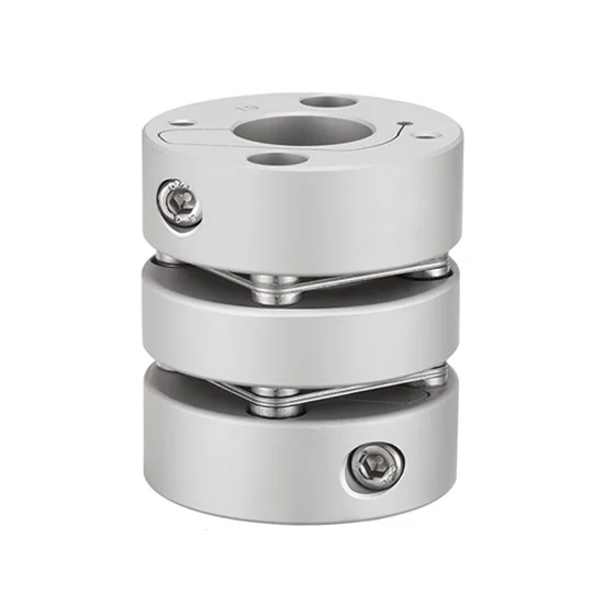
Two diaphragms coupling bore 8mm to 16mm, rated torque 10 N.m, internal clamping, easy installation. Shaft sleeve made of high-strength aluminum alloy, high torque, can accurately control shaft rotation.
Specification
| Model | ATO-SC-GLM3950 |
| Length | 50mm |
| Width | 39mm |
| Bore | 8mm to 16mm |
| Rated Torque | 10 N.m |
| Allow Eccentricity | 0.22mm |
| Allowable Deflection Angle | 1.5∠° |
| Allowable Axial Deviation | ±0.45 |
| Allowable Speed | 10000 RPM |
| Static Torsional Stiffness | 4050N.m/rad |
| Moment of Inertia | 3.0 x 10⁻⁵ |
| Weight | 125g |
| Certificate | ISO9001, REACH, RoHS |
| Warranty | 12 Months |
Bore 8mm to 16mm Diaphragm Coupling Dimension (unit: mm)
| d1/d2 Inner Diameter Size | Φd | L | LF | LP | S | φd3 | F | M | Tightening Torque |
| 8-9-9.52-10-11-12-12.7-14-15-16 | 39 | 50 | 14.9 | 11.2 | 4.5 | 17.5 | 6.0 | M4 | 3.5 N.m |
Details
Keyway
| Shaft Diameter | Keyway Standard Machining Dimensions | Keyway Size | |||
| d1/d2 | b | t | (bXh) | ||
| Width of groove | Tolerance | Depth of groove | Tolerance | ||
| φ6~φ7.9 | 2 | ±0.0125 | 1 | ±0.10 | 2×2 |
| φ8~φ10 | 3 | 1.4 | 3×3 | ||
| φ10.1~φ12 | 4 | ±0.0150 | 1.8 | 4×4 | |
| φ12.1~φ17 | 5 | 2.3 | 5×5 | ||
| φ17.1~φ22 | 6 | 2.8 | 6×6 | ||
| φ22.1~φ30 | 8 | ±0.0180 | 3.3 | ±0.20 | 8×7 |
| φ30.1~φ38 | 10 | 3.3 | 10×8 | ||
| φ38.1~φ44 | 12 | ±0.0215 | 3.3 | 12×8 | |
| φ44.1~φ50 | 14 | 3.8 | 14×9 | ||
| φ50.1~Ф58 | 16 | 4.3 | 16×10 | ||
| φ58.1~φ65 | 18 | 4.4 | 18×11 |
Keyway Machining Standard Drawing
Tips: How to install the diaphragm coupling?
- Wipe clean the dust and dirt on the surface of the installation shaft, and apply a thin layer of engine oil or lubricant.
- Clean the inner hole of the diaphragm coupling, and apply oil or lubricant.
- Insert the diaphragm coupling into the installation shaft; if the aperture is too tight, be careful not to hit the installation with a hammer or hard metal.
- After the positioning is completed, first press the diagonal direction and gently tighten the screw with a torque wrench (the specified tightening torque 1/4).
- Increase the strength (1/2 of the specified tightening torque) and repeat the fourth step.
- Tighten the tightening torque according to the specified tightening torque.
- Finally, tighten the fixing screws in the circumferential direction.
- When disassembling, please proceed with the device completely stopped, loosen the locking screws one by one.
Reviews
There are no reviews yet.