
Description
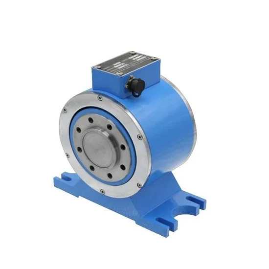
Rotary torque sensors have capacity range from 20Nm, 50 Nm, 100 Nm to 5000 Nm. Torque sensor capacity can be customized according to customer requirements. You can buy a signal converter with 4-20mA/ 0-5V/ 0-10V output or RS485 communications to use with ATO rotating torque sensor.
Specification
| Model | ATO-ZJ-AF | |
| Rotary Torque Sensor | Shipping Weight | 12~45kg |
| Capacity Range * | 0-20 Nm ~ 0-5000 Nm | |
| Accuracy * | 0.2%F·S, 0.1%F·S | |
| Power Supply * | ±15V ±5% DC (≥50mA), 24V DC | |
| Output Signal * | 10kHz±5kHz, 4-20mA, 0-5V, 0-10V (add signal converter, with a 5m connecting cable), RS485 | |
| Speed Signal | 60-2000 pulse/turn | |
| Max. Speed | 6000 rpm | |
| Temperature Drift on Zero | <0.1%F·S/10°C | |
| Operating Temperature | -20°C~+70°C | |
| Humidity | ≤90%RH | |
| Insulation Resistance | >500MΩ | |
| Stability | 0.3%F·S/year | |
| Safety Overload | 150%F·S | |
| Breaking Load | 200%F·S | |
| Sensitivity | 1±0.2 mv/V | |
| Power Consumption | 4W | |
| Bridge Voltage | DC 10V | |
| Material | Alloy steel | |
| Protection Class | IP65 | |
| Electrical Connection | Circular connector | |
| Wiring | Red: V+, Blue: V-, Green: Speed output, Yellow: Torque output, Black: GND | |
| Cable Length | 2m (Φ5mm), or other customizable lengths | |
| Signal Converter | Power Supply | ±15V DC, 24V DC (±0.4V) |
| Power Supply Dissipation Power | Less than 1W | |
| Response Time | ≥100mS | |
| Conversion Accuracy | ±0.1%F·S | |
| Signal Input | Optoelectronic isolation. It is used with rotary torque sensor. | |
| F/V Signal Output | 0-5V, 0-10V | |
| F/I Signal Output | 4-20mA | |
| Operating Temperature | -20°C~+60°C | |
| Humidity | 0-90%RH | |
| Wiring | ±15V DC: Red: V+, Blue: V-, Green: Speed output, Yellow: Torque output, Black: GND 24V DC: Red: 24V DC, Blue: Signal-, Green: Speed output, Yellow: Torque output, Black: GND |
|
| Overall Dimension (mm) | 158*95*55 (L*W*H) | |
| Istallation Dimension (mm) | 143*43, 4-M3 |
Rotary Torque Sensor Dimensions (unit:mm)
| Capacity Range | H | H1 | D1 | D2 | n-d1*Depth | L1 | L2 | L3 | L4 | L5 | L6 | d2 | h |
| 20Nm | 185 | 100 | 52 | 66 | 6-M6*10 | 2 | 2 | 115 | 135 | 45 | 80 | 7 | 12 |
| 50Nm | 185 | 100 | 52 | 66 | 6-M6*10 | 2 | 2 | 115 | 135 | 45 | 80 | 7 | 12 |
| 100Nm | 185 | 100 | 52 | 66 | 6-M6*10 | 2 | 2 | 115 | 135 | 45 | 80 | 7 | 12 |
| 200Nm | 195 | 105 | 52 | 66 | 6-M8*12 | 3 | 3 | 125 | 150 | 60 | 90 | 7 | 12 |
| 500Nm | 205 | 105 | 55 | 70 | 8-M8*12 | 3 | 3 | 130 | 160 | 60 | 90 | 9 | 15 |
| 1000Nm | 213 | 110 | 60 | 80 | 8-M10*16 | 5 | 5 | 160 | 200 | 70 | 100 | 11 | 15 |
| 2000Nm | 213 | 110 | 60 | 80 | 8-M10*16 | 5 | 5 | 160 | 200 | 70 | 100 | 11 | 15 |
| 5000Nm | 286 | 150 | 80 | 136 | 8-M16*25 | 5 | 5 | 210 | 250 | 80 | 120 | 17 | 20 |
Tips: What factors affect the torque sensor output signal?
- The device of the torque sensor should ensure that the coaxiality between the motor end and the load end is within 0.03-0.05mm. When the torque sensor works under the condition of poor coaxiality, the output data of it will be unstable. Long-term work under this condition will damage the torque sensor.
- The field electromagnetic disturbance also has a great impact on the output signal of the torque sensor. The disturbance can be alleviated by connecting with an isolator to the power supply, or adding a magnetic ring to the cable.
- The unstable power supply will also affect the signal output of the torque sensor. You can use a unique switching power supply for the torque sensor.
Reviews
There are no reviews yet.